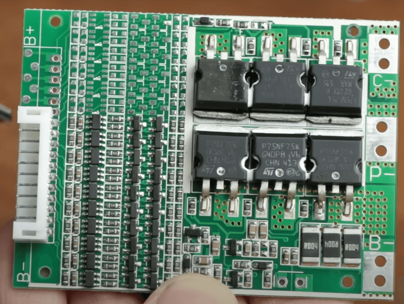
Multi-cell battery management power stage: per-cell voltage-sense dividers and balancing resistors drive a six-device bank of ST P75NF75 TO-247 power MOSFETs for charge/discharge and balancing paths, with B+/B−/C−/P− high-current terminals and 0.4 µH gate-drive inductors.
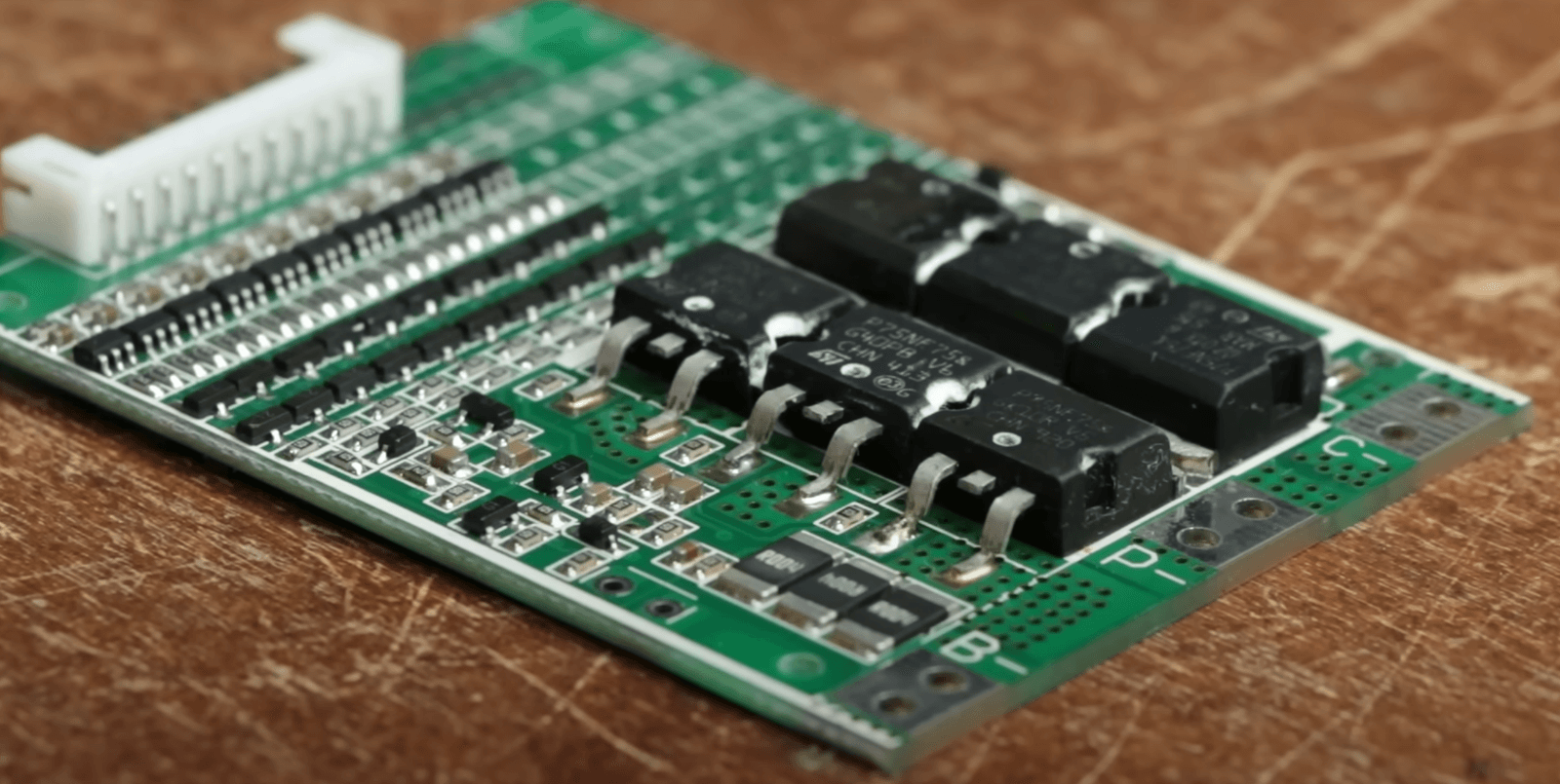
Populated BMS control board — three socketed 8-pin ICs with legible STMicroelectronics markings, SMD resistor/capacitor arrays, a fine-pitch connector, and edge power pads silkscreened B− / P− / C−.
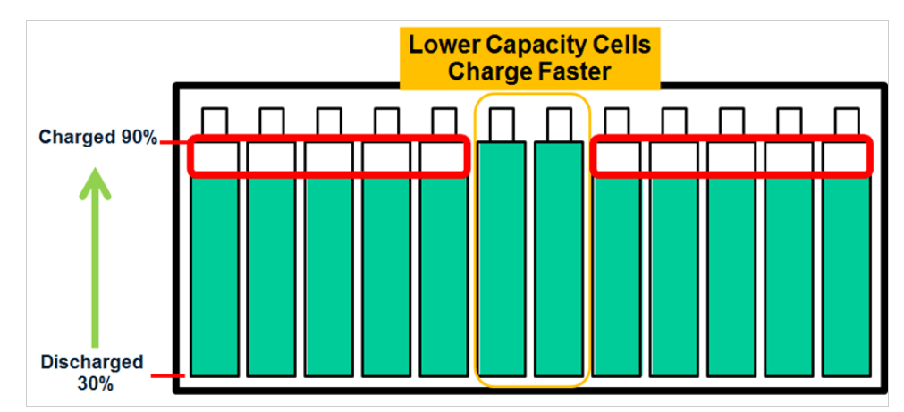
Series-pack charging behavior: lower-capacity cells pull ahead in state-of-charge under shared charge current. The BMS design targets capacity-matched cells plus active balancing to prevent overcharge of fast cells and premature low-voltage cutoff on lagging ones.
.png)
Block-level wiring of the high-voltage safety chain: battery positive rail energizes the high-voltage contactor, whose output feeds the shutdown circuit aggregating LVMS, HVMS, shutdown buttons, IMD and HVBMS fault sources before driving the HV load. Includes enable/trigger and current-sense/comm routing.
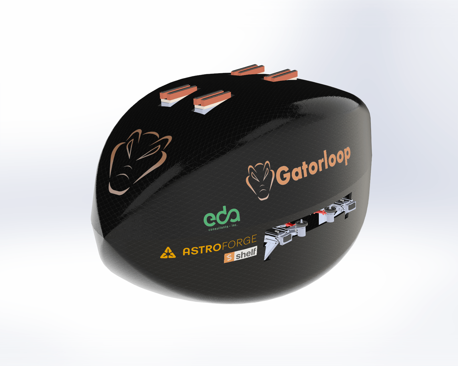
3D model of the pod with section cut exposing internal packaging: structural frame, actuation hardware, cabling and harness routing, and panel integration — systems-level layout and clearance work inside the shell.
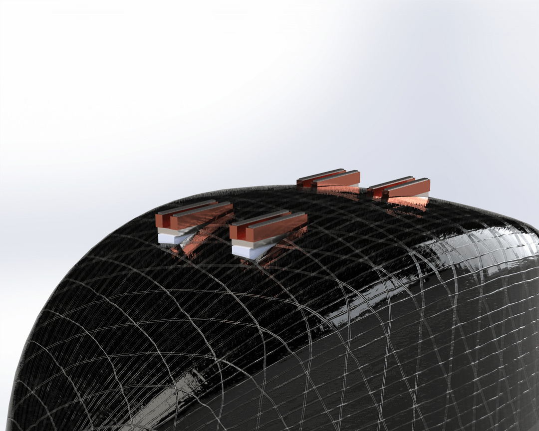
Finite-element mesh draped on the pod shell geometry with four electrical contact/terminal blocks positioned on the crown — structural analysis prepared alongside the electrical interface placement for the shell.
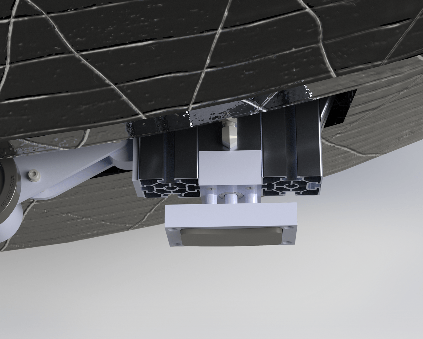
Nadir-pointing instrument package on standoffs from an aluminum extrusion, bracket-mounted to the shell — load path, clearances and fastener detail modeled for the payload bay.
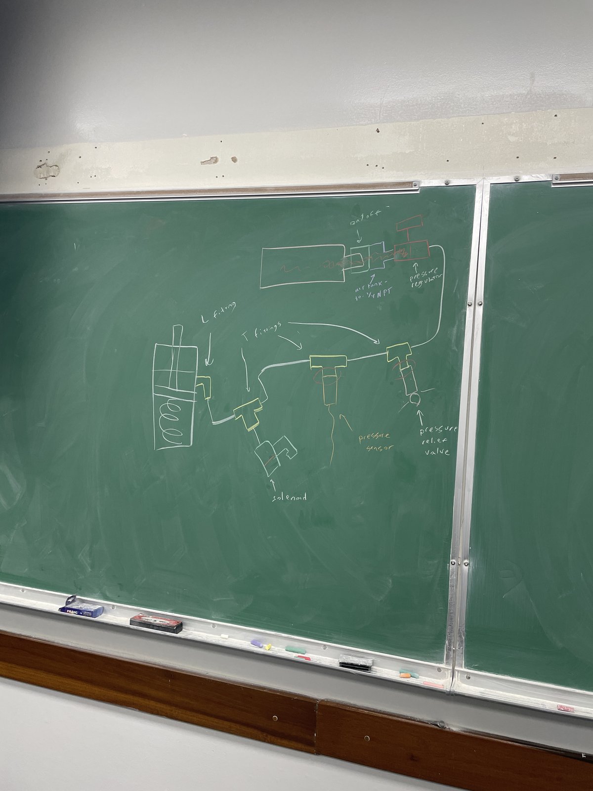
Hand-drawn fluid-power circuit: 1/4 NPT air tank → pressure regulator → T/L-fitting distribution manifold → spring-return cylinder, with solenoid actuation (electrical interface), pressure-sensor feedback, and a pressure-relief valve for safety.
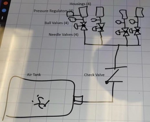
Formalized P&ID of the air distribution: single tank → check valve → common header branching into four identical channels, each with a needle valve (flow control), ball valve (isolation) and pressure regulator feeding a brake housing.
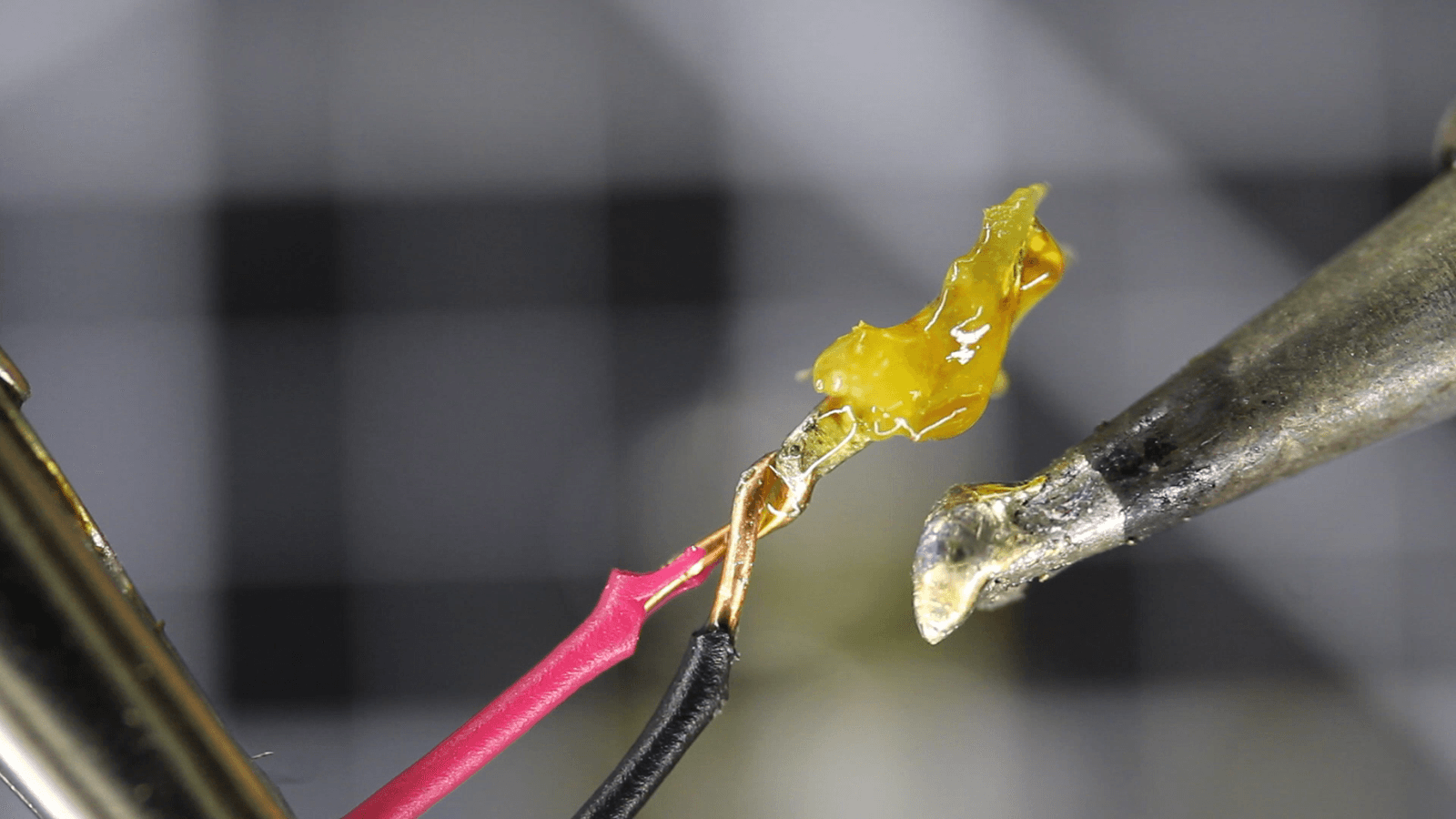
Hand-soldered joint with strain relief and hot-melt insulation — representative of the workshop/bench work across the electrical sub-team: wire splicing, interconnects and power-bank builds (LTspice + hands-on).
.png)
Three-phase brushless motor with finned aluminum housing, mounting flange and keyed shaft, three lugged phase leads. Motor and controller selection and spec analysis (CIRCE MS2223 datasheet work) for the FloRiders powertrain.
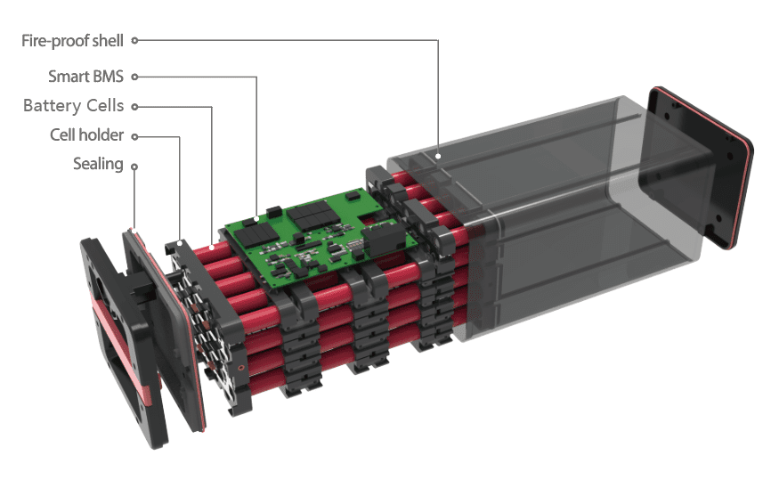
Exploded-view analysis of the pack: cylindrical cell grid in rigid holders, smart-BMS board mounted on the stack, sealing gasket at the end plate, and fire-resistant shell — the basis for the 21700-cell module design below.
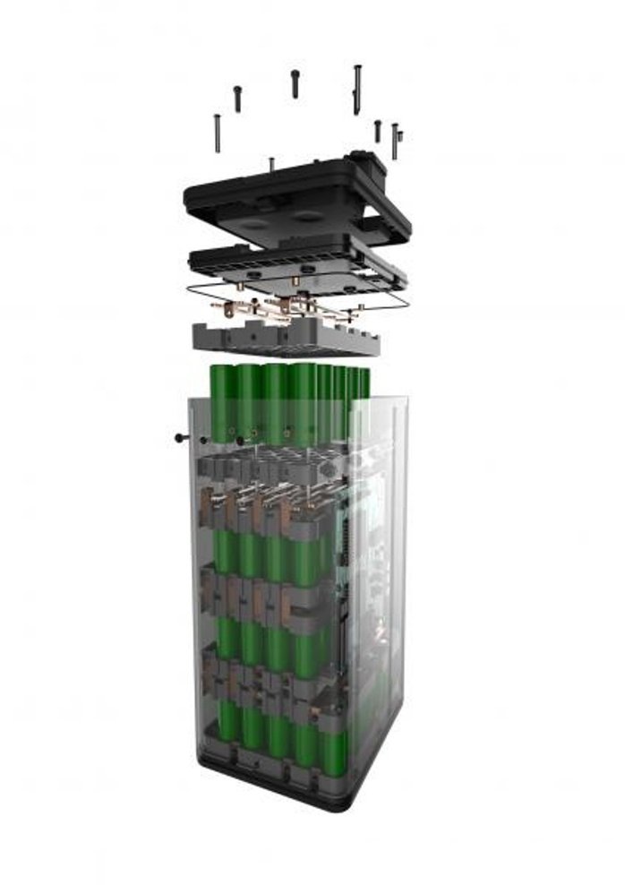
SolidWorks model of the battery pack module prototype: 21700 cells in a see-through housing with copper busbars and strips for series/parallel interconnect, terminal/contact layer, cell holders, cover and clamp fasteners. Parts: Cell_Model_21700, Copper_Bus_Bar, Copper_Strip, Battery_Pack_Module_Prototype.
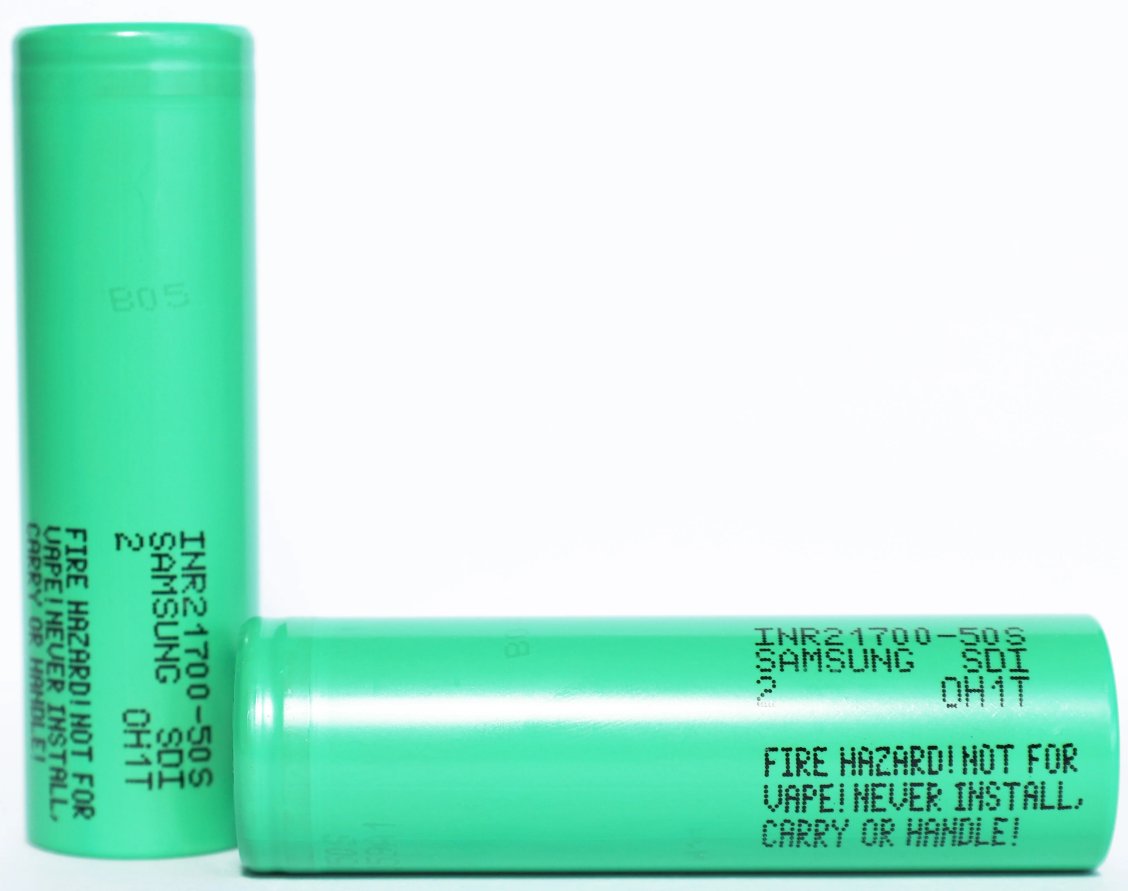
Physical cells selected for the pack: Samsung SDI INR21700-50S — 21 mm 21700 format, ~5000 mAh nominal capacity, blended NMC chemistry with a flat discharge curve suited to the pack's balancing strategy.
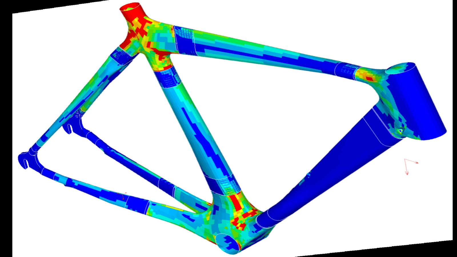
Finite-element stress analysis of the frame: loads concentrate at the head-tube, bottom-bracket and seat-cluster junctions while slender tubes carry mainly axial load — used to validate structure sizing and safety factors.
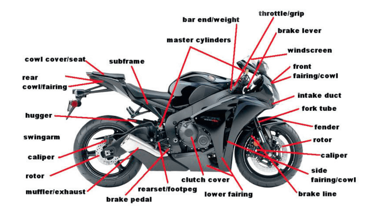
Annotated parts identification of the reference motorcycle — the top-down breakdown used to scope sub-team assignments across structures, brakes, powertrain, and electrical.
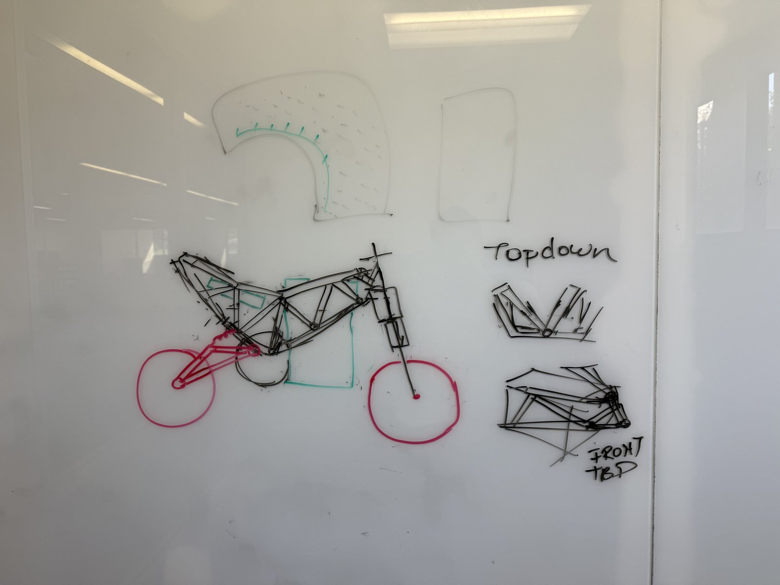
Early hand sketch of the frame concept that seeded the structures design — napkin sketch → requirements → SolidWorks → FEA, the full design workflow across both teams.